MID-ATLANTIC REGION, U.S.A
Nicholas Boccia
Construction Management Option
Part 1-Project Background
Trinity Plaza is located in a residential area in the Mid-Atlantic Region, U.S.A. Many of the building materials used for the construction of this project are post industrial recycled materials, and more than three quarters of its waste will be recycled. The building will feature 14–foot high ceilings, and amenities such as a massage room, food vendors, valet bicycle parking rooftop conference center with an outdoor terrace, and a basketball court.
Building Statistics
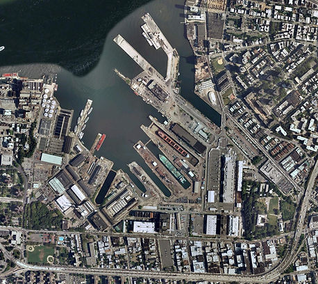
Trinity Plaza,
Mid-Atlantic Region, U.S.A
Photo Courtesy of Google Maps
General Building Data
Building Name:
Trinity Plaza
Location and Site:
The location of Trinity Plaza is 1128 Trinity Ave, Mid-Atlantic Region, U.S.A. The site is located on the corner of Trinity Ave and Washington St.
Building Occupant Name:
Tenant information not released upon
owners request
Type of Building:
Trinity Plaza is a commercial office
building. The first floor consists
of rentable retail space.
Size:
Whole building: 675,000 GSF
Commercial: 525,000 SF
Retail: 100,000 SF
Roof: 50,000 SF
Total Height: 264 FT
Project Delivery Method:
Design-Bid-Build
Number of Stories:
16 Story Building:
1 level of retail use, 15 levels of technology and small scale manufacturing tenants. The roof will consist of water harvesting terraces that serve for recreational purposes as well as to help contribute to LEED silver certifications.
Date of Construction:
Start- 5/2/2015
End- 5/24/2017
Construction Budgeted Cost:
$276,500,000
Construction Actual Cost:
$275,400,000
Overall Project Cost:
$350,000,000

All Photos are Courtesy of S9 Architects
Project Team
This information is not being released upon request of the owner.
Developer- Rudin Development, Boston Properties
Architect- S9 Architects
Architecture
The structure of Trinity Plaza is stepped into four setbacks. Each of these setbacks will consist of its own roof garden. The floor-to-ceiling windows are a unique curtain wall that clad the exterior, which mimics the original design of Trinity Plaza’s early 20th century industrial buildings. The shell of the building will be concrete that wraps around the façade in which windows will be placed in a diagonal zig-zag format to give the structure a unique futuristic look. The idea for this design is to try and move away from steel structures and move towards composite systems.

All Photos are Courtesy of S9 Architects

Sustainability Features
This building will be achieving a goal to reach LEED silver. Some key sustainability features will be the roof setbacks which will have roof gardens and natural water harvesting systems from rain. This will be considered one of the largest rooftop farms. There will also be a sewer project upgrade to improve water conservation and storm water management throughout the site. Roof mounted wind turbines will also be used to collect and store energy to be used throughout the building. Bicycle racks and lanes will be integrated into the designed so that employees can travel to work more efficiently which can lower emissions. Using green technologies such as energy star roofs, energy efficient windows, energy efficient lighting, solar powered trash compactors and street lamps will all help contribute to the buildings overall sustainable goal.
Building Codes
2008 New York City Building Code
2008 NYC Mechanical Code
2008 NYC Plumbing Code
2008 NYC Fuel Gas Code
Structural ASCE -10/ACI 318-11
Zoning Information
Trinity Plaza is located in a commercial zone in the Mid-Atlantic Region, U.S.A
Building Enclosure

All Photos are Courtesy of S9 Architects
Glazed Aluminum Curtain wall
The façade of this building is limited with the amount of materials used. The curtain wall system consists of framing with internal reinforcing as needed. Concrete panels and metal louvers are used as well and will be painted with primer finishes. The curtain wall system is thermally broken from the interior in order to tolerate both vertical and lateral motion. The framing system will accommodate egress door, terrace doors, and precast concrete clad panel system. The precast concrete panels will be placed on an aluminum sub frame that will be mounted to the curtain wall unit.
Concrete Clad Panel System
These panels consist of punched windows that allow for vertical load carrying elements at the jambs of the windows and horizontal members, which can be connected to the jamb members. The overall objective of this system is to provide lateral resistance for horizontal loads. It is important to note the limited amount of structural connections between adjacent and horizontal panels in this design because the panels are used as a lateral-force-resisting system. From this the design stresses will be limited so that the vertical stacks of panels can act independently, which ultimately limits the temperature performance effects.
Roofing System
The roofing system consists of 4”corrugated metal deck that has an overlaying EPDM 3 layer rubber roofing system. This system consists of one thermoplastic polyolefin layer, fluid applied insulator layer and another layer of tar that will be torched to the metal decking. This roofing is considered to be extremely light in weight, elastic, and tough.
Part 2- Engineering Systems
Structural System
The foundation consists of 18” steel pipes that will be piled into the ground. 79”x79”x49” V-Column pile caps will be laid on top of the steel piles along with a 4’ square footing. Finally an 18” concrete slab will be poured to support the structure of the building. Overall the buildings structural system is supported by SOG foundation, grade beams, structural piles, and footings accompanied by a backfill of crushed concrete. The structure above grade will consist of W14 wide flanged columns that will span several stories. The columns range from W14x43 to W14x665. Between the spans of the columns are girders and wide flanged beams to support each floor and slab. These beams and girders vary in a range from W24-W76. The entire buildings structural system will be supported by a steel frame. The steel frame will consist of concentrically W12x65 braced frames that resist lateral loads through a vertical concentric truss system. The axes of these members will align at the joints of the structure.
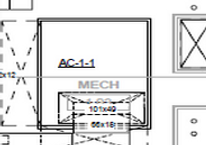
Mechanical System
The major mechanical system in the building consists of 31 self contained air handling units that have 2 units per floor. Each of the units are located in the center interior core of the building The Units are broken down into ACU-A,B,C,D,E,F. These supply airflow of these units vary in a range from 14,000 CFM- 41,000 CFM. These units will individually supply the east and west sides of the building. Three cooling towers are located on the rooftop- penthouse area along with boilers and condenser pumps. VAV control boxes will be used to serve amenity spaces. The commercial spaces will be composed of glycol and electric unit heaters.
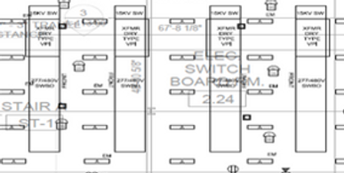
Electrical System
Two 13.8 kV feeders serve as the buildings power source. Feeders are located in two manholes on the east side of the buildings perimeter. For each transformer that supply a panel with an isolated ground bus will have an isolated ground conductor in each conduit of the secondary feeder. The utility connections are located on ground level and feed 4 main switchboards that range from 1,000-4,000 Amps, consisting of 3 phase, 4 wire feed. Power is then distributed to 41 (277/480) panel boards which consist of 2-3 panel boards per floor.Lastly, a 15 kV switchgear is used to control, protect and isolate electrical equipment.


Cooling Towers
Air Handling Unit